
What's on this page
- Before you start: what you need and what to leave alone
- Step 1: Rule out the easy explanations first
- Step 2: Read the label on the back of the module
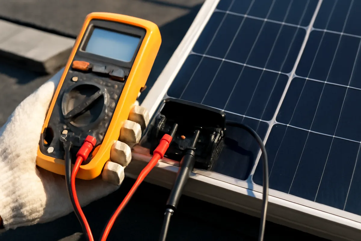
- Step 3: Choose a meter and set it up correctly
- Step 4: Measure open-circuit voltage
- Step 5: Measure short-circuit current
- Step 6: Compare your readings against the label
- What the label actually promises
- Why real readings sit below the rated figures
- What Voc and Isc each tell you
- A worked example: testing one module on a bright afternoon
- What a real reading looks like against the label
- Where the gap between nameplate and reality comes from
- Module, string, or inverter: narrowing it down
- Why voltage and current are not the same as power
- Where the safe testing line sits
- When the app is the better instrument
- What testing cannot tell you
- Common mistakes when testing solar panel output
- Troubleshooting: when the readings look wrong
- Your solar panel output testing checklist
- The bottom line
Short answer: Test a solar panel's output by measuring two readings with a properly rated meter and comparing them to the label on the module's back: open-circuit voltage, which shows the module is alive, and short-circuit current, which tracks sunlight and shows whether it is delivering. Real readings sit below the label because roof cells run hotter and light is weaker than in a test chamber. Test only one disconnected module at ground level.
How to test solar panel output is a question every owner eventually asks, because a solar array is one of the few things you own that never tells you it is unwell. It sits there in the sun looking identical on the day it makes its full output and on the day one module has quietly stopped contributing, and the only way to close that gap is to measure. Testing output means learning two readings, open-circuit voltage and short-circuit current, learning where they come from on the module’s own label, and learning why a healthy module almost never reads exactly what its sticker says. It also means learning where the sensible homeowner test ends, because a photovoltaic array produces direct current for as long as light falls on it, cannot be switched off by throwing a shade over one module, and does not forgive improvisation.
This walkthrough covers six steps: rule out the ordinary explanations, read the module label, choose and set up a meter you can trust, measure open-circuit voltage, measure short-circuit current, then compare both against the label and work out whether the evidence points at one module, one string, or the inverter. Where our note on monitoring solar production teaches you to read what the app reports, this one teaches you to put a probe on a module and read it directly. Keep the companion calculator open as you go, because it turns your two label figures and your two measured figures into the comparison the whole test rests on.
Key takeaways
- The only correct reference for your module is the label on its own back: rated open-circuit voltage and rated short-circuit current, measured in a lab under standard test conditions.
- Real readings sit below the label most of the time, because cells are hotter and sunlight is weaker on a roof than in a test chamber. That gap is physics, not a fault.
- Voltage tells you the module is alive and moves mainly with temperature; current tracks the sunlight and is the reading that reveals whether the module is actually delivering.
- Homeowner testing stops at one accessible, already-disconnected module at ground level, in dry conditions, with a properly rated meter. Roofs, inverter interiors, combiner boxes, and any alternating current wiring belong to a qualified technician.
- A reading that is far off in the same light and conditions points a professional at the right place. It does not diagnose the fault, and it should not be treated as if it does.

Before you start: what you need and what to leave alone
Testing output is one of the few solar tasks where the preparation matters more than the procedure, because the procedure itself takes about ninety seconds and the preparation is what keeps it uneventful. A photovoltaic module is a current source that switches itself on the moment light reaches the glass. There is no off switch. Covering one module in a series string does not de-energise the rest, and direct current arcs, unlike the alternating current ones most people have unconsciously calibrated against, do not extinguish themselves when the circuit opens. That single physical difference is the reason solar work has its own trade and its own tooling.
What a competent owner needs before starting is short: the module’s label figures, a meter with the right ratings, undamaged leads, dry weather, bright sun, and a module that is genuinely accessible at ground level and already disconnected from everything else. That last condition does most of the safety work. A spare module, a ground-mounted module a technician has isolated for you, or a small standalone panel is a reasonable test subject. A module bolted to a roof and wired into a live string is not.
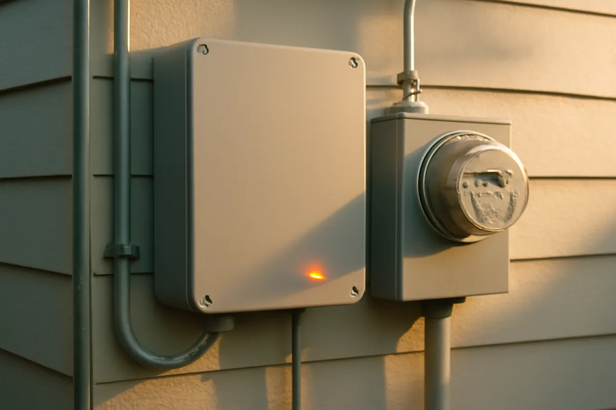
What to leave alone is equally short and not negotiable: the inside of the inverter, any alternating current wiring, the combiner box, any enclosure that has to be opened, any connector that is part of a live string, and anything at all that requires you to be on a roof. Those go to a qualified solar technician or licensed electrician. Our note on how solar systems can fail explains why the connector and enclosure side of an array is treated with such care.
Step 1: Rule out the easy explanations first
Reach for the meter last, not first. The overwhelming majority of low-output complaints resolve without any measurement at all, and working through the free explanations first saves both effort and risk. Start with the sky and the calendar. Output falls with cloud, haze, low winter sun angles, and short days, and a reading taken on an overcast afternoon will look alarming while describing a perfectly healthy system. Our note on output under cloud covers how much light level alone moves the number.
Next look at the glass. Dust after a dry spell, pollen, salt film, bird droppings, or a drift of leaves in the lower corner all cut output measurably, and all of them are visible from the ground with a decent look. Our cleaning walkthrough covers restoring a soiled array safely. Then look for shade that was not there before: a tree that has grown into the afternoon sun, a new dormer, a neighbour’s addition, a satellite dish. Shade that arrives at the same time each day leaves a signature in the production curve that is unmistakable once you know to look.
Finally, check the monitoring itself. A gateway that has lost its internet connection reports zeros while the array produces normally, and mistaking a communication dropout for a production failure is the single most common false alarm in home solar. Confirm the last successful reading is recent. Only when weather, soiling, shade, and connectivity are all genuinely ruled out does a physical measurement start earning its keep.
Step 2: Read the label on the back of the module
Every photovoltaic module carries a label, usually on the back of the laminate, that lists its electrical characteristics. Those figures, and only those figures, are the correct reference for your test. Rated power in watts tells you the module’s nameplate size. Open-circuit voltage, written as Voc, is the voltage the module produces across its leads with nothing connected. Short-circuit current, written as Isc, is the current it delivers when its two leads are joined directly. Maximum power voltage and current, usually written Vmp and Imp, describe the operating point where the module makes the most power, which is where the inverter tries to hold it.
Write down Voc and Isc before you touch anything, because those are the two numbers your measurements will be compared against. They are printed for standard test conditions, which is a laboratory reference: a defined light intensity, a defined light spectrum, and a cell temperature of 25 degrees Celsius. Many labels also carry a second set of figures for a more realistic operating temperature, and those will be lower. Knowing which set you are reading matters, because comparing a real reading against the wrong column produces false alarm every time.
Two more things on that label are worth noting. Manufacturers publish tolerance bands and temperature coefficients that describe how much the figures legitimately move, and those vary by product, so read the ones on your own module rather than assuming a general rule. Our note on what panel efficiency percentages actually mean explains how these label figures relate to the specification sheets people compare when shopping.
Step 3: Choose a meter and set it up correctly
The meter is where most of the genuine hazard in this task sits, because an underrated instrument fails in ways that put energy where you are standing. Four things need checking before a probe goes anywhere. First, the direct current voltage range must comfortably exceed the voltage you expect to see. Second, the meter needs a measurement category rating appropriate to the installation, which is the standard that governs how a meter behaves during a transient event rather than during normal use. Third, the current input must be fused. Fourth, the current range must exceed the module’s rated short-circuit current from the label.
That fourth point stops more home tests than any other, and it should. A great many inexpensive meters cap their current input well below what a modern module can deliver in strong sun. Pushing more through an input than it is built for is how meters, and occasionally hands, come to grief. If the label current exceeds what your meter is rated for, the correct outcome is to skip the current test entirely and note that a technician with proper instruments needs to complete it. Skipping a measurement you cannot take safely is a successful test, not a failed one.
Then inspect the leads. Cracked insulation, exposed metal near the probe shoulder, loose banana plugs, or a lead that has been repaired with tape all disqualify the meter. Set the function switch deliberately before connecting anything, confirm the leads are in the correct jacks for the measurement you are about to take, and never move a lead between the voltage and current jacks while it is connected to a module.
Step 4: Measure open-circuit voltage
Open-circuit voltage is the first measurement because it is the lower-risk one and because it answers the most basic question: is this module generating at all. Take it on a single module that is already disconnected from everything else, at ground level, in dry conditions, with the sun on the glass. Set the meter to direct current voltage on a range above what you expect from the label. Put the black lead in the common jack and the red lead in the voltage jack. Keep your free hand clear of any conductive surface, and where the geometry allows, keep it out of the circuit entirely, which is the habit that has protected electricians for a century.
Touch the probes to the module’s two output terminals, positive to red, negative to black, with firm contact and without letting the probe tips touch each other or anything else. Read the number and let it settle. A reversed reading, showing the right magnitude with a minus sign, simply means the probes are on the opposite terminals from what you assumed; it is information, not a fault. Note the reading, the time of day, the approximate air temperature, and how clear the sky was, because you will need all four to interpret it.
Then step back and take the second reading a minute later to confirm it is stable. What you are looking for is a number in the same neighbourhood as the label figure. Modestly below it in warm sun is ordinary. Well above the label on a cold, brilliantly clear morning is also ordinary. Near zero on a bright day, or a wildly unstable reading, is where you stop and hand the job over.
Step 5: Measure short-circuit current
Short-circuit current is the reading that tells you whether the module is actually delivering, and it is the one that demands more of both you and your instrument. Only attempt it if Step 3 confirmed your meter’s current input is fused and rated above the label’s Isc figure. Move the red lead to the current jack, set the function switch to direct current amps on a range above the label figure, and confirm both before anything touches the module. Moving a lead into the current jack while it is connected to a live module is the classic way to create a fault, so make the change with the leads free.
Take the reading in the strongest, most direct sun you can arrange, on clean glass, with the module facing the sun squarely and nothing shading any part of it. Touch the probes to the two terminals, read the current, and remove the probes promptly rather than holding the short indefinitely. Note the reading alongside the same context you recorded for voltage: time, sky, temperature, and how square the module was to the sun. Because current scales almost proportionally with light, the conditions are not background detail here, they are half the measurement.
Then put the leads straight back into the voltage jacks. A meter left configured for current is a hazard the next time someone picks it up expecting a voltage range, and that is a genuinely common way that meters die. Enter both readings into the companion calculator alongside your label figures to see how they compare before you start interpreting anything.
Step 6: Compare your readings against the label
Now do the actual work of the test, which is comparison rather than measurement. Divide your measured open-circuit voltage by the label’s rated Voc, and your measured short-circuit current by the label’s rated Isc. Two percentages fall out, and those two percentages, read together and in the light of the conditions you recorded, are the finding. Neither number alone means much. Voltage at a plausible fraction of its rating with current at a plausible fraction of its rating, in the conditions you actually had, describes a module doing its job.
The interpretation runs directionally, not diagnostically. Voltage somewhat below the label on a hot afternoon is the temperature effect and nothing more. Voltage above the label on a cold clear morning is the same effect in reverse. Current well below its rating in hazy light, at a low sun angle, or through a film of dust is exactly what should happen, because current follows the light. What is worth attention is a reading that the conditions cannot explain: near-zero voltage in bright sun, or current at a small fraction of its rating when the sky is genuinely clear, the glass is clean, and the module is square to the sun.
At that point the test has done its job, which is to point somewhere rather than to conclude something. Bring the readings, the label figures, the conditions, and any monitoring data to a qualified solar technician or your installer. Most systems carry equipment and workmanship coverage, and our note on solar warranties explains why an early, well-documented call so often costs nothing.
What the label actually promises
Standard test conditions are a laboratory reference, not a weather forecast, and understanding that removes most of the confusion around output testing. The rating is taken at a defined light intensity, with a defined light spectrum, at a cell temperature of 25 degrees Celsius. All three matter. The light intensity is roughly what a clear midday sky delivers to a surface facing the sun directly, which your roof achieves only for a narrow window on good days. The spectrum assumption approximates sunlight after a defined path through the atmosphere, which shifts with sun angle and haze. The temperature assumption is the one that almost never holds, because a module in full sun runs far hotter than the surrounding air.
That gap is not a manufacturer trick, it is the price of having a comparable number at all. Without a fixed reference, no two modules could be compared, and a specification sheet would be meaningless. The rating exists so that a buyer can weigh one product against another, and every manufacturer publishes against the same reference for exactly that reason. Our note on how solar panels work covers the cell physics underneath these figures.
The practical consequence is that you should expect your module to underperform its label most of the time and treat that as correct behaviour. The useful question is never whether the reading matches the rating, because it will not. It is whether the reading matches the rating in a way the conditions explain. That reframing is what separates a productive test from an anxious one.
Why real readings sit below the rated figures
Four separate effects push a real reading below the laboratory figure, and they stack. Temperature is the largest for voltage: silicon cells lose voltage as they warm, and a module in direct sun can run well above the ambient air temperature. This is why an array often produces its highest instantaneous voltage on a cold, bright winter morning rather than in high summer, which surprises almost every new owner.
Light intensity is the largest for current. A module produces current in near proportion to the light striking it, so anything that reduces that light reduces the current directly: thin cloud, haze, a sun angle away from perpendicular, morning and evening geometry, or shorter winter days. This is also why a current reading taken at four in the afternoon is not comparable to one taken at solar noon, and why comparing your reading against the label without noting the conditions is meaningless.
Then come the losses that are about the installation rather than the physics. Soiling on the glass blocks light before it reaches a cell. Wiring runs, connections, and the mismatch between modules in a series string all shave a little. Conversion in the inverter takes its share on the way to alternating current. And over the years, gradual degradation trims the ceiling slightly, as our note on how long panels last describes. None of these are faults; together they are why real systems are modelled with a derate factor rather than at nameplate.
What Voc and Isc each tell you
The two measurements are not interchangeable, and understanding what each one is sensitive to is what makes the pair diagnostic. Open-circuit voltage is remarkably insensitive to light level. A module in weak, diffuse light will often show a voltage close to what it shows in strong sun, because voltage in a photovoltaic cell depends on the physics of the junction far more than on how many photons are arriving. That is convenient in one way: it makes voltage a reliable liveness check that works in imperfect conditions. It is treacherous in another: a module can show near-normal voltage while producing almost no usable energy.
Short-circuit current is the opposite. It tracks the incoming light closely, which makes it the honest measure of whether a module is delivering, and also the measure that is worthless unless you record the conditions alongside it. Halve the light and you roughly halve the current. Shade a strip across the cells and the current drops sharply even though voltage may barely move.
Together they cover each other’s blind spots. Voltage present and current absent points one way; both present and proportionate points another; both absent in bright sun points a third. That is why any competent test takes both, and why a single voltage reading, which is what most casual home testing produces, is the weakest possible evidence of health.
The pairing is complementary by design rather than merely convenient: voltage is the liveness check that barely needs light, current is the delivery check that needs it directly. The two readings also share a floor worth knowing so you never mistake it for a fault. In full darkness a module’s open-circuit voltage falls toward zero along with its short-circuit current, because there is no light to separate charge across the junction in the first place, and this is also why a grid-tied inverter stops trying to export overnight once the array in front of it has nothing left to convert. A reading taken too early in the morning or too late in the evening can land in that same near-zero territory for the ordinary reason that there simply is not enough sun yet, not because anything is wrong. Neither reading, incidentally, is power, which is a point worth its own section below.
A worked example: testing one module on a bright afternoon
Take one household through it end to end. The Alvarez family notices their monitoring showing a persistent shortfall on clear days, and after ruling out weather, a dusty spell, and a new tree, their installer isolates one ground-level module for them to check while a service visit is scheduled. Its label reads, for this illustration only, 40 volts open-circuit and 10 amps short-circuit at standard test conditions. Those are round teaching numbers chosen for the arithmetic, not figures from any real product, and your own label will read differently.
At two in the afternoon under a clear sky, with clean glass and the module turned square to the sun, they measure 37.4 volts open-circuit and 8.6 amps short-circuit. Dividing through: voltage at about 94 percent of rating and current at about 86 percent. Both land where the conditions predict. The module is hot, so voltage sits a little under its 25 degree rating. The light is strong but it is mid-afternoon rather than solar noon, so current sits a little under its full-irradiance rating. Nothing here calls for a repair.
They then check a second isolated module in the same light, minutes apart, and read 12 volts and 0.4 amps, roughly 30 percent and 4 percent of the same ratings. The conditions are identical, so the conditions cannot explain the difference. That is the whole finding, and it is where their testing stops: two documented readings, taken the same way in the same light, one of which the physics does not account for. It goes to the technician with the numbers attached. Run your own two pairs through the companion calculator to produce the same comparison.
What a real reading looks like against the label
Because so much confusion comes from expecting the label figure, it helps to see roughly where real readings tend to land under different conditions. The chart below shows an illustrative pattern of measured readings as a share of the label rating. It is a teaching pattern for calibrating expectations, not a measurement of any product, and your own module, climate, and instrument will shift every bar.
Where a real reading tends to land
Illustrative measured value as a share of the module's own label rating, by condition.
Illustrative shares, not measurements or specifications. The pattern is the point: voltage stays near its rating and moves mainly with temperature, while current moves with the light and can drop to a small fraction of its rating without anything being wrong.
Read down the bars and the two personalities separate cleanly. Voltage occupies a narrow band and can sit above the rating when cells are cold, which is why a voltage reading alone rarely proves much. Current occupies an enormous range driven entirely by the sky, which is why a current reading without recorded conditions is uninterpretable. The discipline that follows is simple: never judge a current reading without writing down what the sun was doing, and never conclude a module is healthy on voltage alone.
Where the gap between nameplate and reality comes from
It also helps to see how the total shortfall between a nameplate figure and real delivered output tends to divide up, because it explains why derating is standard practice rather than pessimism. The chart below splits an illustrative gap by cause. The exact shares will not match your system, but the ordering is the durable lesson: conditions dominate, and equipment faults are the smallest slice.
Where the gap between nameplate and reality comes from
Illustrative split of the shortfall between label rating and real delivered output. Sums to 100%.
Illustrative shares, not a universal split. Roughly two thirds of the gap between a nameplate figure and real output traces to heat and light alone, which is why a reading below the label is the expected outcome rather than a symptom.
The order tells you where to look and in what sequence. Heat and light explain most of any gap and cost nothing to account for, so account for them first. Soiling is next, common and often fixable from the ground, and our maintenance field guide covers the routine. Wiring, mismatch, and conversion losses are baked into the design and are not something a homeowner test will change. Only after all of those are accounted for does a genuine equipment fault become the plausible explanation, and that is a technician’s call rather than a meter’s.
Module, string, or inverter: narrowing it down
Once you know a shortfall is real, the useful question is where it lives, and the answer usually falls into one of three tiers. A single-module problem shows up as one module reading unlike its neighbours in identical light, or, on a system with panel-level hardware, as one low tile in an otherwise even grid. It is the most localised finding and often the easiest to resolve, because the rest of the array carries on.
A string-level problem shows up differently. On a system with a string inverter, modules are wired in series, so a break anywhere in the chain, or a connection problem, can take a whole run of modules out at once. The signature is a large, abrupt drop in production rather than a gentle sag, and on a multi-string system, one string reading near zero while another reads normally. That comparison is diagnostic on its own and does not require you to touch anything.
An inverter-level problem takes the whole system down or throws a fault code, and it is the one you are most likely to see over a system’s life, since the inverter is the component with the shortest typical service life. Our note on microinverters versus string inverters explains why the architecture decides how visible each tier is. In all three cases the narrowing is the homeowner’s contribution and the opening of anything is not. Combiner boxes, inverter interiors, and string connectors are qualified-technician work without exception.
Why voltage and current are not the same as power
A point that trips up almost everyone: neither of the readings you just took is the module’s power output. Open-circuit voltage is measured with no current flowing, so the power delivered at that moment is zero. Short-circuit current is measured with essentially no voltage across the terminals, so the power delivered at that moment is also zero. The two measurements bracket the module’s behaviour at its two extremes, and its actual working power sits somewhere in between, at the point where the product of voltage and current is largest.
That point is what the label’s maximum power voltage and current describe, and it is what your inverter spends its life hunting for. Inverters run a tracking routine that continuously adjusts the operating point to keep the array near its maximum power point as light and temperature shift through the day. This is why the inverter, not the module, decides how much power actually flows, and why a module can test fine while the system still underproduces.
The practical consequence is that Voc and Isc testing answers the question “is this module capable” rather than “is this system delivering.” For the second question, production data over time is the better instrument. Our note on reading production data covers the kilowatt-hour side, and the two approaches are complementary rather than competing: the app tells you something changed, the meter tells you where to look.
Where the safe testing line sits
It is worth stating the boundary plainly rather than leaving it implied, because the difference between a safe test and a dangerous one is not skill, it is scope. Inside the line: a single module, at ground level, already disconnected from everything else, in dry conditions, with clean undamaged leads and a meter whose ratings you have checked against the label. Reading a status light or an error code on the outside of an enclosure. Looking at glass and frames from the ground. Photographing what you see. Recording numbers.
Outside the line, without exception: anything on a roof, anything requiring an enclosure to be opened, anything involving the inverter interior, anything on a combiner box, anything on the alternating current side of the system, and separating any connector that is part of a live string. Direct current connectors are designed to be mated and unmated by trained hands with the correct tool and only when no current is flowing, and getting that wrong produces an arc that will not stop on its own.
There is also a stop-immediately list that overrides everything else: cracked or clouded glass, discoloured or browned cells, moisture inside a laminate or an enclosure, a scorched or melted connector, a burnt smell, a warm spot, a breaker that will not stay set, or simply anything you do not recognise. In all of those cases the right move is to stop, leave the equipment alone, and call a qualified solar technician or licensed electrician. Our note on choosing an installer covers finding someone properly credentialed.

When the app is the better instrument
For most owners most of the time, the monitoring app beats the meter, and it is worth being clear about why rather than pretending a multimeter is the primary tool. Monitoring watches continuously, across every module the system reports on, in every weather condition, without anyone climbing anything or touching anything. A meter gives you one reading, on one module, at one moment, in whatever conditions happened to prevail. As evidence, continuous data usually wins.
Monitoring is also better at the comparison that matters, which is the same system against itself over time. A clear day this month against clear days last month tells you far more than a single absolute reading against a laboratory rating ever will, because it holds every variable except the equipment roughly constant. On systems with panel-level hardware, monitoring localises a weak module in seconds, which is exactly the job a meter would otherwise be doing the hard way.
Where the meter earns its place is confirmation and isolation: when monitoring is ambiguous, absent, or offline, when a specific module is suspected and has been safely isolated, or when there is no monitoring at all, which is common on small standalone panels, off-grid setups, and older systems. Read the monitoring walkthrough as the routine and treat this one as the follow-up. If your monitoring is dark, fixing that is usually a higher-value move than any single measurement.
What testing cannot tell you
Being honest about the limits of a home test is what keeps its results useful. A pair of readings cannot tell you why a module is behaving badly. Low current in good light is consistent with several very different internal conditions, and distinguishing between them takes instruments a homeowner does not have and should not improvise: infrared imaging that finds hot spots, curve tracing that maps the module’s full behaviour rather than its two endpoints, and insulation testing that checks for paths current should not be taking.
It also cannot tell you whether a module is safe. Nothing about a voltage figure reveals a degraded connector, a compromised laminate seal, or a mounting problem, and a module reading perfectly can still have a physical issue that matters more than its electrical output. That is why the visual inspection carries as much weight as the numbers, and why the stop-immediately list exists independently of anything the meter says.
Finally, it cannot settle a warranty claim. Manufacturers and installers have their own diagnostic procedures and evidence requirements, and a homeowner reading is an input to that process rather than a substitute for it. What your test genuinely produces is a documented, well-conditioned observation that gets a professional to the right place faster. That is a real contribution, and overstating it into a diagnosis is the one mistake that turns a careful test into a liability.
Common mistakes when testing solar panel output
The same handful of errors account for most of the wasted effort, false alarms, and genuine hazard in output testing, and each one is easy to avoid once it is named.
- Expecting the label figure. Standard test conditions are a laboratory reference your roof will rarely reproduce. A reading below the label in warm, real-world sun is the normal outcome, and treating it as a fault produces endless false alarms.
- Recording the number but not the conditions. A current reading without the time, the sky, the temperature, and the module’s angle to the sun cannot be interpreted by you or by anyone you show it to. Conditions are half the measurement.
- Testing voltage only. Voltage is nearly insensitive to light, so a module can read close to normal while delivering almost nothing. Voltage alone confirms life, not performance.
- Using an underrated meter. A current input that is unfused or rated below the module’s short-circuit current is the most serious hazard in this task. If the ratings do not clear the label figure, skip the current test and say so.
- Leaving the meter in current mode. A meter put away configured for amps is a trap for the next person who reaches for a voltage reading. Return the leads to the voltage jacks every time.
- Crossing the line. Climbing onto the roof, opening an enclosure, or pulling a connector on a live string turns a low-risk task into a serious one instantly. Those are qualified-technician jobs regardless of confidence.
- Testing in the wet. Moisture on connectors, leads, glass, or hands changes the risk profile completely. Dry conditions are not a preference here, they are a precondition.
Avoid these seven and output testing stays what it should be: a brief, low-risk observation that either reassures you or gives a professional a useful starting point.
Troubleshooting: when the readings look wrong
What if I read zero volts on a bright day? Check the obvious instrument problems before concluding anything about the module: the meter’s function setting, the range, the lead placement in the jacks, the battery, and whether the probe tips are making real contact rather than resting on a coated or oxidised surface. Test the meter on a known source to confirm it works. If the meter is proven and the module still reads zero in good light, that is a genuine finding and the point at which it goes to a technician rather than to more probing.
What if the voltage reads higher than the label? That is usually correct behaviour rather than an error. Cells produce more voltage when they are cold, so a bright, cold morning can push open-circuit voltage above the rating printed for 25 degrees. This is precisely why system designers size for cold-weather voltage rather than for the nameplate figure. A modestly high reading in cold clear conditions is expected; an implausibly high one suggests you are measuring more than one module in series.
What if the current is far below rating but the voltage looks fine? Check the light first, because that combination is exactly what weak or oblique sunlight produces, and it is the single most common false alarm in current testing. Then check the glass and check for shade across any part of the module, since shading a strip of cells cuts current sharply while barely moving voltage. If the sun is strong and direct, the glass is clean, and nothing is shading it, the reading is unexplained and belongs with a professional.
What if two identical modules read differently in the same light? That is the most informative result the test can give you, because it holds every condition constant and isolates the equipment. Repeat both readings to rule out probe contact and meter drift, then document both with the conditions and hand them over. Do not attempt to work out which internal mechanism is responsible, because that determination needs imaging and curve tracing rather than two endpoint readings.
Your solar panel output testing checklist
Use this as the save-and-act summary. Work it top to bottom and the test stays brief, low-risk, and genuinely useful.
- Rule out weather, season, soiling, new shade, and a monitoring dropout before reaching for any instrument at all.
- Read the module's own label and write down rated open-circuit voltage and rated short-circuit current, noting which conditions column you are reading.
- Confirm your meter's direct current voltage range, measurement category rating, fused current input, and current range against the label figures.
- Inspect the leads for cracked insulation, exposed metal, or loose plugs, and reject the meter if anything is damaged.
- Test only a single module at ground level that is already disconnected from everything else, in dry conditions and bright sun.
- Measure open-circuit voltage first, keeping your free hand clear, and let the reading settle before recording it.
- Measure short-circuit current only if the meter clears the label figure, then return the leads to the voltage jacks immediately.
- Record the time, sky condition, approximate temperature, and the module's angle to the sun alongside every reading.
- Divide each reading by its label rating and judge the two percentages together, in the light of those conditions.
- Stop at once for cracked glass, discoloured cells, moisture, scorching, a burnt smell, or anything unfamiliar.
- Send anything involving the roof, the inverter interior, a combiner box, alternating current wiring, or a live string connector to a qualified solar technician or licensed electrician.
- Hand your documented readings, label figures, and conditions to your installer, since most systems carry coverage that makes an early call free.
The bottom line
Testing solar panel output is a comparison, not a verdict. You read two numbers off the module’s own label, you measure the same two on a module you can reach safely, and you ask whether the difference between them is something the temperature and the sunlight explain. Most of the time it is, because a laboratory rating and a hot roof in real weather are not the same thing and were never meant to be. When it is not, the value of the exercise is not that you have found the fault, it is that you have given a professional a well-documented place to start.
The figures throughout, the illustrative 40 volt and 10 amp label, the 37.4 volt and 8.6 amp healthy reading, the second module at 12 volts and 0.4 amps, and the shares in both charts, are teaching examples chosen to build the instinct rather than measurements or promises about any product. What does not change is the boundary. An array makes direct current whenever the sun is on it, it cannot be switched off, and its arcs do not stop on their own, so homeowner testing lives at ground level on one isolated module and ends the moment a roof, an enclosure, a live string, or any alternating current wiring enters the picture. Work your own label and readings through the companion calculator, read this alongside the monitoring walkthrough and the maintenance field guide, and the meter becomes what it should be: a short, careful second opinion.
WattBarn publishes this walkthrough as consumer education about photovoltaic measurement, not as electrical, engineering, or safety instruction for your particular installation. Every voltage, current, percentage, and chart share above is an illustrative teaching figure rather than a specification, a measurement, or a claim about any product, and only the label on your own module carries figures that apply to it. Photovoltaic arrays generate direct current whenever light reaches the glass, they cannot be switched off, and their faults do not behave like the household wiring most people are used to, so nothing here should be read as permission to work on a roof, inside an inverter, on a combiner box, on alternating current wiring, or on any live string. Those tasks, and any decision about whether equipment is damaged or should be replaced, belong to a qualified solar technician or licensed electrician working to the codes and standards in force where you live.
Frequently asked questions
How do I test solar panel output?
You test a module by measuring two things with a meter and comparing them against the figures printed on the module's own label: open-circuit voltage, which is the voltage across the leads with nothing connected, and short-circuit current, which is the current the module pushes when its two leads are joined through the meter. Both are taken in bright sun, in dry conditions, on a module you can reach safely and that is already disconnected from everything else. The comparison is the whole test: voltage that lands in a sensible band below the label figure on a warm day, and current that scales down with the light you actually have, describe a module doing its job. Readings far off in the same conditions describe something worth a technician's attention. Anything involving the inverter interior, alternating current wiring, a combiner box, or a trip onto the roof is not a homeowner test and should go to a qualified solar technician or electrician.
What should a solar panel read on a multimeter?
There is no universal number, and anyone who quotes you one without seeing your label is guessing. Every module carries its own rated open-circuit voltage and short-circuit current on a sticker on the back, measured under standard test conditions in a laboratory, and those two figures are the only correct reference for your specific module. What you can expect is a relationship rather than a value. Open-circuit voltage tends to sit somewhat below the rated figure when the cells are hot and can edge above it when they are cold, because voltage in a silicon cell falls as temperature rises. Short-circuit current tracks the sunlight almost proportionally, so it approaches the rated figure only in strong, direct midday sun on clean glass and falls well below it under haze, low sun angles, or soiling. Read your own label first, then judge your reading against it.
Why is my solar panel voltage lower than rated?
Usually because the label figure was measured at a cell temperature of 25 degrees Celsius under full test irradiance, and your roof almost never delivers those conditions at the same time. Silicon cells lose voltage as they heat, so a module baking in afternoon sun genuinely produces less voltage than its sticker promises, and that is normal physics rather than a defect. On a cold, bright winter morning the same module can read above its rated voltage for the same reason in reverse. Beyond temperature, a slightly low voltage reading can come from a meter on the wrong range, worn test leads, poor probe contact, partial shade across the module, or measuring something other than a single module. A reading modestly below the label in warm sun is expected. A reading dramatically below it, or near zero on a bright day, is the kind of gap that deserves a qualified solar technician rather than more home testing.
Can I test a solar panel with a regular multimeter?
A basic meter can read the voltage of one small module, but a household meter is often the wrong tool for a home array, and using the wrong one is where people get hurt. You need a meter with a direct current voltage range that comfortably exceeds what you are measuring, an appropriate measurement category rating for the installation, a fused current input, and a current range that exceeds the module's rated short-circuit current. Many inexpensive meters cap their current input well below what a modern module can deliver, and pushing more through them than they are built for can damage the meter or worse. Test leads must be undamaged, with no cracked insulation or exposed metal. If you cannot confirm your meter's ratings against the numbers on the module label, the honest answer is not to attempt the current test at all and to have a qualified technician bring instruments built for the job.
Is it safe to test solar panels myself?
Parts of it can be, within tight limits, and parts of it are not homeowner work at all. A solar array generates direct current whenever light falls on it, it cannot be switched off by covering one module, and direct current arcs do not self-extinguish the way alternating current arcs tend to, which is why solar faults are treated seriously. Reasonable homeowner testing means a single module you can reach at ground level, already disconnected from everything else, in dry conditions, with a meter rated for the job, keeping one hand clear where you can. Unreasonable testing means climbing onto a roof, opening an inverter, pulling connectors on a live string, or touching a combiner box or any alternating current wiring. Those belong to a qualified solar technician or licensed electrician. If any part of the equipment is wet, damaged, scorched, or simply unfamiliar, the correct action is to stop, leave it alone, and make a phone call.
How do I know if a solar panel is bad?
You rarely prove it at home, and it is worth being honest about that. What testing gives you is direction, not a diagnosis. A module reading close to its neighbours in the same light and roughly in line with its label is behaving; a module reading dramatically differently under identical conditions is the one to point a professional at. Visible signs matter as much as numbers: cracked or shattered glass, a browned or discoloured area on the cells, moisture inside the laminate, a scorched or melted connector, or a warm spot you can feel. Any of those means stop testing and call someone qualified, because damage changes the risk profile entirely. Panel-level monitoring, where the system has it, often localises a weak module faster than a meter does. A meter confirms what monitoring suspects; the repair decision and the warranty claim belong to your installer.
Should I test open-circuit voltage or short-circuit current?
Both, because they answer different questions, and either one alone can mislead you. Open-circuit voltage is the easier and lower-risk measurement and it tells you the module's cells are connected and generating at all, which is why it is the first thing anyone checks. It is also stubbornly insensitive to light level, so a module in weak sun can show near-normal voltage while producing almost nothing useful, and that is exactly how a low-output module hides behind a healthy-looking voltage reading. Short-circuit current is the measurement that tracks the light, so it is the one that reveals whether the module is actually delivering. It also demands more of your meter and more care from you. If your meter cannot safely handle the label's current figure, take the voltage reading, note that the current test was not possible, and let a technician with proper instruments complete the picture.
When should I stop and call a solar technician?
Stop at the first sign of damage, at the first thing you do not recognise, and at the boundary of anything you cannot reach from the ground. Specific triggers include cracked or clouded glass, discoloured cells, a burnt smell, scorching or melting on a connector or enclosure, water where water should not be, a breaker that will not stay set, an inverter showing a fault, or a reading so far from the label that it makes no sense in the conditions you have. Stop also if the work would require you to go onto the roof, open an enclosure, separate connectors on a live string, or touch anything on the alternating current side of the system. Those are qualified-technician tasks in every case. Most systems carry equipment and workmanship warranties, so calling early usually costs nothing and often saves the repair bill entirely.