

What's on this page
- What ballasted solar racking actually is
- Why weight instead of a bolt
- Where ballasted racking shows up
- The parts of a ballasted racking system
- How engineers size the ballast
- Field, perimeter, and corner zones
- Why the chart shows a jump at the corners
- Tilt angle, exposure, and parapets
- A worked example: sizing ballast for one array
- Where that weight actually sits
- The other half of the equation: roof load capacity
- Ballasted vs penetrating: a real trade-off
- Membrane protection and roof walkability
- Snow, wind, and climate
- The hybrid approach: weight plus a few true anchors
- Common mistakes when specifying or buying ballasted racking
- Maintenance and inspection over the system’s life
- Permitting and the engineering letter
- What ballasted racking costs, and why
- When ballasted racking is the wrong call
- Troubleshooting: questions people actually ask
- Your ballasted racking checklist
- The bottom line
Short answer: Ballasted solar racking holds an array on a flat or low-slope roof using weight, usually precast concrete blocks loaded onto tilted metal trays, instead of bolting the racking through the roofing membrane. An engineer calculates how much weight each part of the roof needs by working out the wind uplift the array will see, with corner and edge zones demanding far more ballast per square foot than the open field of the roof. The trade is simple to state and genuinely consequential: no penetrations to leak, against real added weight the structure has to carry.
Most people picture a solar array as something bolted down, and on a pitched residential roof that picture is correct: rails run across the rafters, lag bolts go through the shingles into the framing, and the roof gets flashed around every one of them. Flat and low-slope roofs, the kind found on garages, additions, mobile homes, and the vast majority of commercial buildings, often take a completely different approach. The racking is not fastened to the structure at all. It sits on top of the roof, tilted toward the sun, and it is held in place by sheer weight.
That approach has a name, ballasted racking, and it solves a real problem: a membrane roof is only as good as the number of holes nobody has put in it, and a solar array that lasts twenty-five years is a long time to trust a sealant joint over every bolt. This explainer covers what a ballasted system actually is, how the ballast weight gets calculated, why a roof’s corners need dramatically more of it than the middle, where the method fits and where it does not, and what the real cost and maintenance trade-offs look like next to a penetrating mount. Our roof replacement briefing and ground mount cost comparison cover the other mounting decisions a property owner weighs against this one. Run your own numbers through the companion calculator as you read.
Key takeaways
- Ballasted racking holds an array down with weight, usually precast concrete blocks on tilted trays, instead of bolting the racking through the roofing membrane.
- It is built for flat and low-slope roofs, generally under about 10 degrees of pitch, where a tray can sit still on the roof surface and resist sliding and uplift through weight and friction.
- Required ballast is not uniform across the roof. Corner and edge zones, where wind uplift concentrates, typically need far more weight per square foot than the open field of the roof.
- The trade against a penetrating mount is real in both directions: no roof penetrations to flash and maintain, against genuine added dead load the roof structure has to be shown to carry.
- Every weight figure in this explainer is an illustrative teaching number. The actual ballast schedule for any roof comes from a site-specific engineering calculation, never from an article.
What ballasted solar racking actually is
Strip away the brand names and a ballasted racking system is three things working together. A metal tray or frame, usually aluminum or coated steel, holds one or more modules at a fixed tilt angle. The tray sits directly on the roof surface, typically on a protective pad that spreads its point load rather than concentrating it on one spot of membrane. And weight, almost always precast concrete in block or paver form, sits in a cradle built into the tray or stacks on a dedicated ballast pan, pressing the whole assembly down against the roof.
Nothing in that assembly touches the structural deck. The roofing membrane, whatever it is, single-ply, modified bitumen, or a built-up system, stays physically unbroken under the racking. That single fact is the entire reason the method exists: a roof that never gets drilled cannot develop a leak at a hole that was never there.
Trays are usually ganged in rows, sometimes tilted east-west in a sawtooth pattern to pack more capacity into a given roof area at a shallower effective tilt, and sometimes tilted uniformly south-facing like a conventional array. The choice between those layouts is itself a production-versus-density trade that a designer makes against the specific roof’s shape and the owner’s priorities, which our sizing briefing covers from the production side.
Why weight instead of a bolt
The logic is worth stating plainly, because it explains every design choice that follows. A penetrating mount resists wind uplift through the strength of a fastener anchored into structural framing. That is an extremely strong connection, which is exactly why it is the default on a pitched residential roof where the roofing material, usually shingle or tile, is not itself the weatherproofing membrane in the way a flat roof’s single-ply or built-up system is.
On a flat or low-slope roof, the membrane is doing double duty as both the weatherproofing layer and, in many cases, the only thing standing between the building and water intrusion across a huge, mostly flat area where water does not run off quickly. Every penetration through that membrane is a seam that has to be properly flashed, inspected, and maintained for as long as the array sits there, and a flat roof has none of the natural shedding that a steep pitched roof uses to keep water moving away from a joint.
Ballasted racking sidesteps that risk entirely by never creating the penetration in the first place. The cost of avoiding it is that the racking now has to resist the same wind forces using only its own weight and the friction between its base and the roof surface, which is a fundamentally different, and in some ways harder, engineering problem than driving a bolt into a rafter.
Where ballasted racking shows up
The method is the default on flat commercial roofs: big-box retail, warehouses, schools, office buildings, and similar structures almost always use a ballasted or hybrid ballasted system when the roof is flat, because the roof area is large, the membrane is expensive to replace, and the building typically has the structural reserve capacity to carry the added dead load.
On the residential side it is less common but far from rare. Flat or very low-slope roofs turn up on additions, garages, porches, row houses, some mid-century modern homes, and mobile or manufactured homes, and any of those can be a candidate for ballasted racking rather than a penetrating mount, provided the structure can take the weight. Our types of solar panels briefing and roof replacement briefing both assume a pitched asphalt roof as the default case, because that is still the most common residential situation, but a flat-roofed property is exactly where this explainer’s method becomes the relevant one.
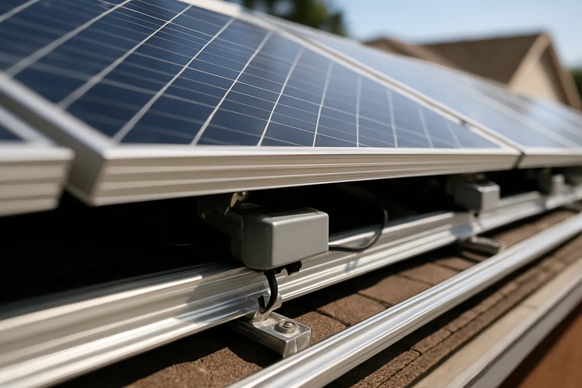
The parts of a ballasted racking system
A complete system has a short list of components, and understanding each one explains where the engineering effort actually goes. The tray or frame is the structural member that holds the module at its tilt angle and provides the pocket or pan where ballast sits. Its own weight counts toward the total dead load the roof carries, even before any concrete is added.
The ballast itself is usually precast concrete, supplied as solid blocks, interlocking pavers, or poured into a tray-integrated pan, chosen because concrete is cheap per pound, dimensionally consistent, and does not degrade meaningfully from weather exposure over the system’s life. The protective pad sits between the tray’s feet and the membrane, spreading the point load of the tray and its ballast over a larger footprint so the membrane and the roof deck beneath it are not asked to carry a concentrated load they were not built for.
Inter-row and inter-tray connectors tie adjacent trays together, which matters because a connected row of trays behaves differently under wind than a row of isolated trays, generally resisting sliding and uplift better as a linked system. And on roofs with meaningful wind exposure, some designs add a limited number of true penetrating anchors at the most demanding zones, which is the hybrid approach covered later in this explainer.
How engineers size the ballast
This is the part that genuinely matters and the part most homeowner-facing content skips. Ballast is not sized by rule of thumb. A structural or solar engineer calculates the wind uplift force the array will experience using a recognized wind-load engineering standard, commonly ASCE 7 in the United States, combined with the project’s specific wind speed zone, the building’s height and exposure category, the array’s tilt angle, and its position on the roof.
That calculation produces a required holding-down force for each part of the roof, and the ballast schedule converts that force into pounds of concrete per square foot of array footprint, distributed according to where on the roof the array sits. The output is not a single number for the whole roof. It is a map, with different zones of the roof requiring different ballast rates, which is the subject of the next section.
Nothing about this process can be shortcut by an article, a rule of thumb, or a contractor’s memory of what worked on the last job. Wind speed zones, exposure categories, and the applicable code edition are all local and project-specific, and the only correct source for your own ballast schedule is the stamped engineering calculation prepared for your specific roof.
Field, perimeter, and corner zones
Wind does not pull on a flat roof evenly, and this is the single most important mechanical fact in ballasted racking design. As wind moves across a building, it separates and accelerates at the roof’s edges and especially at its corners, creating localized zones of much higher uplift pressure than the open interior, or field, of the roof experiences. Wind engineers divide a flat roof into these zones, commonly called field, perimeter, and corner, precisely because the uplift demand is so different between them.
The practical consequence is that a ballast schedule is never a flat rate across the whole roof. The interior field of the array might need a relatively modest ballast rate. A strip running along the roof’s edges needs more. And the corners, typically a relatively small fraction of the total roof area, need the most ballast per square foot by a wide margin, sometimes several times the field rate.
This zoning is why an array positioned with generous setback from the roof edges can sometimes carry meaningfully less total ballast than the identical array pushed out toward the perimeter, and it is a genuine design lever a good installer uses rather than an incidental detail.
Why the chart shows a jump at the corners
The illustrative pattern below shows how a ballast rate typically escalates moving from a roof’s open field toward its corners, holding wind speed and building height constant and changing only the zone. It is a teaching shape built to show the relationship, not a specification for any real project, and your own engineer’s numbers will differ based on your actual site conditions.
Illustrative ballast rate by roof zone
Pounds of ballast per square foot of array footprint, by position on the roof. A teaching pattern, not a code value for any project.
Illustrative rates only, not a code value or a measurement of any real building. A parapet wall, which many commercial roofs have, reduces corner uplift somewhat by disrupting the wind separation that drives it, which is why the exposed no-parapet corner carries the highest illustrative rate here.
Read across those four bars and the shape is the lesson: the field and the corner are not a small adjustment apart, they can be several times apart, and a ballast schedule that applied the field rate everywhere would leave the corners dangerously under-weighted, while one that applied the corner rate everywhere would add enormous unnecessary weight across most of the roof. Zone-specific ballast exists because a flat rate would fail in one direction or waste money in the other.
Tilt angle, exposure, and parapets
Tilt angle feeds directly into the same uplift calculation and pulls in two directions at once. A module tilted up at a steeper angle presents more surface to the wind coming across the roof, which generally raises the uplift force an engineer has to design against. The same steeper tilt also typically improves the array’s energy harvest by pointing the modules closer to the sun’s path, which is the production benefit a designer weighs against the added ballast cost.
Low-tilt or near-flat layouts cut wind exposure and the ballast that goes with it, which is part of why sawtooth, low-tilt commercial layouts are common on large flat roofs: less ballast per row means more rows fit within the roof’s total load budget. The trade is some production per module, recovered partly by simply fitting more modules on the same roof area, an arithmetic our solar sizing reference covers in more general terms.
Building height and exposure category matter too, and in the same direction: a taller building, or one standing in an open, unobstructed location, generally sees higher wind speeds at roof level and needs more ballast for the same array than an identical array on a sheltered, lower building. And a parapet wall, the short wall that runs around the edge of many flat commercial roofs, measurably reduces corner and edge uplift by disrupting the wind separation that concentrates pressure there, which is one reason commercial ballast schedules often differ sharply from what a similar-looking residential flat roof without a parapet would need.
A worked example: sizing ballast for one array
Take one array through the arithmetic to see how the zones actually add up. Picture a 20-module flat-roof array, with each module and its share of tray and spacing accounted for at an illustrative 20 square feet of roof footprint, for a total array footprint of 400 square feet. This is a teaching example with round numbers chosen for the arithmetic, not a specification for any real product or project.
Say the engineering calculation for this specific roof, at this specific wind zone and tilt, comes back with an illustrative field rate of 4 pounds per square foot and a corner-zone rate of 9 pounds per square foot, and that the layout puts about 20 percent of the array’s footprint inside the higher-demand corner and edge zones, with the remaining 80 percent sitting in the open field.
The field portion covers 320 square feet at 4 pounds per square foot, for 1,280 pounds. The corner and edge portion covers the remaining 80 square feet at 9 pounds per square foot, for 720 pounds. Add them together and the array needs 2,000 pounds of ballast in total, one short ton, spread unevenly across the roof rather than applied as a flat rate. At an illustrative 35 pounds per standard concrete ballast block, that works out to roughly 57 blocks. Run your own module count and your own engineer’s rates through the companion calculator to see your version of this same arithmetic.
Where that weight actually sits
The same worked example, viewed as a split of the total ballast weight rather than a rate per zone, shows something easy to miss from the rate chart alone: a relatively small slice of the roof area carries a disproportionate share of the total weight.
Where the ballast weight goes in the worked example
Split of the 2,000-pound illustrative total between the field and the corner and edge zones. Sums to 100%.
Illustrative split from the worked example above, not a measurement of any real project. The corner and edge zone covers a fifth of the array's footprint but carries more than a third of the total ballast weight.
That imbalance is the whole reason zone-based ballast schedules exist instead of a single blanket rate. A roof’s structural capacity is usually also assessed by zone for the same reason: the question is never just “can this roof carry the array’s total weight” but “can this specific patch of roof, right here at the corner, carry what the engineering calculation says has to sit on it.”
The other half of the equation: roof load capacity
Ballast sizing answers one question: how much weight does the array need to stay put. It says nothing about whether the roof can actually carry that weight, which is a completely separate structural question and arguably the more consequential one, because getting it wrong risks the building rather than just the array.
Every roof has a design load capacity set when it was built, covering its own dead weight plus an allowance for live loads like maintenance workers, snow, and ponding water. Adding a ballasted array adds a new, permanent dead load on top of that budget, and the structural question is whether the existing roof framing has enough reserve capacity left to carry it, considering both the total added weight and, just as importantly, where it concentrates.
This is not a question a racking manufacturer’s ballast table can answer on its own, because it depends on the specific building’s framing, not on the array. A property owner considering ballasted racking, especially on an older roof or a residential structure not originally designed with solar in mind, needs a structural assessment of the existing roof alongside the racking’s own ballast calculation. Our roof replacement briefing covers the related question of roof condition and remaining service life, which matters here for a different reason: re-roofing under an installed ballasted array later is its own costly project, covered further down.
Ballasted vs penetrating: a real trade-off
It helps to state the trade-off plainly rather than let either method sound like the obvious winner, because neither is. A penetrating mount creates a known, manageable risk at each fastener, a flashed penetration that needs periodic inspection and eventually re-sealing, in exchange for an extremely strong, well-understood connection that adds comparatively little dead weight to the roof.
A ballasted mount removes that penetration risk entirely but replaces it with a different one: real, substantial added weight that the structure must be shown to carry, often concentrated unevenly at the corners, plus a system that resists uplift through friction and mass rather than a fastened connection, which generally demands a more rigorous site-specific engineering calculation to get right.
Neither approach is universally better. A sound flat commercial roof with ample structural reserve is usually the clear case for ballast. A pitched residential roof with healthy framing is usually the clear case for a penetrating rail mount, which our microinverters versus string inverters briefing and most of this site’s installation content assumes as the default. The interesting cases, an aging flat residential roof, a lightly framed addition, a roof near its load limit already, are exactly where this decision needs a specific engineer’s judgment rather than a general rule.
Membrane protection and roof walkability
Avoiding penetrations does not mean a ballasted system is risk-free for the roof underneath it, and taking that seriously is part of specifying one correctly. The tray feet and the ballast blocks themselves rest on the membrane, and without a protective pad spreading that load, a concentrated point under a tray foot or a block corner can wear or stress the membrane over years of thermal cycling, even without ever puncturing it.
Properly specified systems address this with a dedicated protective pad or slip sheet under every point of contact, chosen for compatibility with the specific membrane type, since different membranes, single-ply, modified bitumen, built-up, have different chemical compatibility requirements for anything placed directly on them. A pad incompatible with the membrane can do its own slow damage even while technically preventing a puncture.
Foot traffic is the other overlooked factor. Installation and later maintenance both put people walking across a roof that was not necessarily designed for routine foot traffic in the first place, and a maintenance plan should include a defined walk path that avoids stepping directly on membrane seams or vulnerable areas. Our maintenance field guide covers panel-level upkeep generally; a flat-roof ballasted array adds this roof-surface consideration specifically.
Snow, wind, and climate
Climate shapes a ballasted design in more than one way, and the two major forces, wind and snow, do not always pull in the same direction. Wind uplift is the force the ballast primarily resists, and it is what most of this explainer has focused on, because it is the force that tries to lift the array off the roof.
Snow adds weight rather than lift, but it adds it unevenly in a way that interacts with the racking’s own tilt. A tilted ballasted tray can shed snow differently than a flat roof surface around it, sometimes accumulating a drift at the base of a row that adds real weight exactly where ballast calculations did not necessarily plan for extra load. Our winter performance briefing covers snow’s effect on production; the structural side covered here is a separate concern an engineer accounts for in a snow-load climate.
Coastal and high-wind regions obviously demand more ballast across the board, but they also more often push a design toward a hybrid approach, discussed next, simply because a pure weight-only solution for the highest wind zones can require more concrete than the roof can structurally support, at which point weight alone stops being a viable answer and a different method has to supplement it.
The hybrid approach: weight plus a few true anchors
When wind demand at the corners or in a high-exposure location would require more ballast than a roof can structurally carry, or more than is economically sensible to ship and place, engineers sometimes specify a hybrid system: a limited number of genuine penetrating anchors placed at the specific zones with the highest uplift demand, typically the corners, while the rest of the array remains purely ballasted.
This is not a failure of the ballasted approach, it is the same engineering logic applied consistently: put the strongest connection exactly where the load is highest, and use the lighter-weight solution everywhere the load allows it. A hybrid design still penetrates the roof far less than a fully bolted array would, concentrating the small number of penetrations at a few carefully flashed, carefully maintained points rather than at every tray.
The decision to go hybrid, fully ballasted, or fully penetrating is entirely a function of the site’s specific wind demand, the roof’s structural reserve, and sometimes the roofing manufacturer’s own warranty terms around penetrations, and it belongs with the project’s structural engineer rather than with a general rule any article could offer.
Common mistakes when specifying or buying ballasted racking
A handful of errors account for most of the problems that show up later, and each is avoidable with the right question asked early.
- Using a generic ballast table instead of a site-specific calculation. Manufacturer tables are a starting reference, not a substitute for an engineering calculation that accounts for your actual wind zone, building height, and layout.
- Treating the roof’s structural capacity as someone else’s problem. The ballast schedule tells you what the array needs. A separate structural assessment tells you what the roof can give. Skipping the second question is how a sound racking design ends up on an unsound roof.
- Ignoring membrane compatibility for the protective pad. A pad that is fine on one membrane type can chemically or physically stress another. Confirm compatibility with your roofing manufacturer, not just your racking supplier.
- Underestimating corner and edge demand. A flat ballast rate applied everywhere is either dangerously light at the corners or wastefully heavy everywhere else. Insist on a zoned schedule.
- Forgetting the re-roofing question. A heavy ballasted array sitting on a membrane that needs replacement in a few years turns a routine re-roof into a major, expensive project. Check the roof’s remaining service life before, not after, installing.
- Assuming ballasted always means lighter installation labor. Moving and placing a ton or more of concrete is its own logistics and labor cost, sometimes offsetting the flashing labor a penetrating mount would have required instead.
Maintenance and inspection over the system’s life
A ballasted array needs a different maintenance eye than a bolted one, focused less on fastener corrosion and more on whether the system is still sitting where it was placed. Periodic inspection should confirm that ballast blocks have not shifted or cracked, that trays remain level and properly seated, and that the protective pad under each contact point is still intact rather than worn through by years of thermal movement.
Roof membrane condition deserves its own look specifically in the areas under and around the racking, since this is exactly the area a routine roof inspection can miss if nobody thinks to lift a tray edge and check. Debris and standing water around tray bases are also worth a look, since flat roofs are more prone to ponding than pitched ones, and water sitting against a tray base for extended periods is not something the original design necessarily accounted for.
None of this replaces a general roof inspection; it adds to it. A maintenance plan for a ballasted array should explicitly include the racking and the roof surface beneath it, not just the modules and the electrical system that our monitoring briefing and maintenance field guide already cover.
Permitting and the engineering letter
Ballasted systems do not escape the permitting process our permitting and interconnection briefing covers in general; if anything, the structural review tends to be more involved, because the building department’s reviewer has to confirm both the ballast calculation and the underlying roof’s capacity to carry it, rather than confirming a bolted connection into framing whose capacity is often more straightforward to verify.
Expect a stamped structural letter or set of calculations from a licensed engineer covering the wind uplift analysis, the zone-by-zone ballast schedule, and confirmation that the existing roof structure can carry the added dead load, especially at the heavier corner and edge zones. This is not a step to shop around on price; it is the document that confirms the installation will not be a structural problem on day one or year fifteen.
Jurisdictions that see a lot of commercial flat-roof solar are generally well practiced at reviewing this kind of package. A residential flat-roof project may be less routine for a given building department, which can mean more questions and a longer review, a timeline factor worth asking about before signing, alongside everything our permitting briefing covers more generally.
What ballasted racking costs, and why
Ballasted hardware typically costs more per watt in racking alone than a comparable penetrating rail system, for straightforward reasons: concrete ballast is heavy and that weight has to be manufactured, shipped, and placed, and the trays themselves are a more substantial, more engineered product than a rail and a set of standoffs.
What ballasted racking can save is labor and materials elsewhere in the install. There is no flashing to install and seal at every mounting point, which is real labor on a penetrating job, and in some cases keeping the membrane unbroken simplifies the project’s relationship with the roofing manufacturer’s own warranty, since many roof warranties treat penetrations as a condition requiring specific disclosure or an approved detail. Ask your roofing manufacturer directly how a planned installation, ballasted or penetrating, interacts with your specific roof warranty, since this varies by manufacturer and is not something a solar installer can authoritatively answer on the roofing company’s behalf.
Net cost against a penetrating alternative depends heavily on roof size, local freight costs for the concrete, labor rates, and the specific wind zone’s ballast demand, so a side-by-side bid for your actual roof is the only reliable comparison. Our general cost briefing covers typical residential pricing, which assumes the more common penetrating pitched-roof case; treat a flat-roof ballasted quote as its own line item to compare rather than expecting it to match that baseline. Note too that the federal residential solar tax credit under section 25D was terminated for property placed in service after December 31, 2025 under Public Law 119-21, so any cost comparison for a residential project today should be run without assuming that credit applies; confirm current incentive status with a tax professional before relying on any figure.
When ballasted racking is the wrong call
Ballasted racking is not the right answer everywhere, and a good installer should say so rather than defaulting to it out of convenience. A steep pitched roof is a poor fit by geometry alone, since weight alone cannot reliably resist gravity pulling a tray down a slope the way it resists wind on a flat plane.
A roof with limited structural reserve, an older building, a lightly framed residential addition, or a roof already carrying other rooftop equipment near its load limit, may simply not have the capacity to accept the added dead weight a ballasted array requires, even where the wind calculation itself is manageable. In that situation a lighter hybrid or fully penetrating design, engineered to add less total dead load, can be the more honest answer, even if it means a few more flashed penetrations.
A roof nearing the end of its service life is also a poor candidate for a heavy, labor-intensive ballasted installation, because re-roofing under an existing array of concrete blocks means a far more expensive project than re-roofing a bare roof. Our roof replacement briefing walks through exactly that sequencing question, and it is worth answering before, not after, a ballasted array goes up.
Troubleshooting: questions people actually ask
Why does my installer want to add a few bolts to an otherwise ballasted design? This is usually the hybrid approach in practice: the engineering found that the corners or a high-exposure zone need more holding force than weight alone can reasonably provide, so a small number of true anchors supplement the ballast exactly where the wind demand is highest. It is a sign of careful engineering, not a compromise.
Can I add more ballast myself if I am worried about wind? No. Adding ballast beyond what the engineering calculation specifies changes the load on the roof structure in ways that calculation did not evaluate, and it can push a roof past its actual capacity even while appearing to make the array safer. Any change to the ballast schedule needs to go back through the engineer who calculated it.
Will ballasted racking void my roof warranty? Possibly, and the honest answer is that only your roofing manufacturer can say, because warranty terms around rooftop equipment vary by manufacturer and sometimes by specific membrane product. Ask before installation, in writing, rather than assuming either way.
Is a ballasted array heavier overall than people expect? Often yes. A ton or more of concrete spread across a modest residential array, as in the worked example above, surprises people who picture racking as a lightweight metal frame. That weight is the entire mechanism the system relies on, not an unfortunate side effect of it.
Your ballasted racking checklist
Use this as the save-and-act summary before specifying or approving a ballasted system.
- Confirm the roof's pitch is genuinely flat or low-slope; ballasted racking is not a fit for a steep pitched roof.
- Get a site-specific wind-uplift and ballast calculation from a licensed engineer, not a generic manufacturer table.
- Get a separate structural assessment confirming the existing roof can carry the added dead load, especially at corner and edge zones.
- Ask whether the design is fully ballasted or hybrid, and understand why wherever a hybrid anchor point is specified.
- Confirm the protective pad under every tray and ballast contact point is compatible with your specific roofing membrane.
- Check the roof's remaining service life before installing; a heavy array complicates a future re-roof significantly.
- Ask your roofing manufacturer in writing how the planned installation interacts with your existing roof warranty.
- Put a walk path and a racking-and-membrane inspection into your ongoing maintenance plan, not just a panel checklist.
- Never add ballast beyond the engineered schedule on your own; any change goes back through the original calculation.
- Get a project-specific cost comparison against a penetrating alternative rather than assuming either method is cheaper.
The bottom line
Ballasted solar racking solves a specific problem, keeping a flat or low-slope roof’s membrane unbroken, by replacing bolted connections with calculated weight. That trade is genuinely good when the roof has the structural reserve to carry it and genuinely wrong when it does not, which is why every real ballast number in this explainer, the 4 pounds per square foot field rate, the 9 pounds per square foot corner rate, the 2,000-pound worked example total, is a teaching illustration rather than a specification, and why the only number that matters for your own roof comes from a licensed engineer looking at your actual building.
The method is not a shortcut and it is not automatically lighter work than a penetrating mount; it is a different set of trade-offs entirely, weight and friction against fasteners and flashing, each suited to a different roof. Get the wind calculation, get the structural assessment of the existing roof, ask about the re-roofing timeline before the array goes up, and treat every ballast figure you see, including the ones here, as a pattern to understand rather than a number to copy. Work your own module count and your engineer’s rates through the companion calculator, then read this alongside the roof replacement briefing and the permitting and interconnection briefing for the rest of the project around it.
WattBarn publishes this explainer as general consumer education about how ballasted solar racking works, not as structural, engineering, or roofing advice for any specific building. Every weight, rate, and percentage above is an illustrative teaching figure chosen to show how the calculation works, not a measurement, a code value, or a specification for any real roof, product, or project. Wind-load standards, required ballast rates, structural capacity, membrane compatibility, and permitting requirements are all site-specific and determined by a licensed structural engineer and your local building department, and nothing here should be treated as confirming that any particular ballast weight, racking product, or design is adequate for your roof. Federal and local incentive rules referenced above, including the termination of the section 25D residential credit, change on schedules this explainer does not control; confirm current rules with a tax professional before relying on them.
Frequently asked questions
What is ballasted solar racking?
Ballasted racking is a way of holding a solar array in place on a flat or low-slope roof using weight instead of bolts through the roofing membrane. The modules sit in tilted metal trays or frames, and precast concrete blocks, pavers, or weighted trays are loaded onto the racking itself, so friction and dead weight resist wind uplift and sliding rather than a fastener driven into the structure below. It is the dominant mounting method on flat commercial roofs and shows up on flat or low-slope residential roofs too, wherever the roofing membrane needs to stay unbroken.
How much ballast weight does a solar array need?
There is no single number, because the required weight is an engineering calculation that depends on wind exposure, building height, roof zone, tilt angle, and the local wind-load standard the structural engineer is working to. As a teaching illustration only, a flat interior area of a roof might call for roughly 4 pounds of ballast per square foot of array footprint, while a corner zone on the same roof, where wind uplift concentrates most sharply, might call for something like double or more of that rate. Your own array's number comes from a site-specific calculation, never from an article.
Does ballasted racking damage a flat roof?
Properly specified ballasted racking is chosen specifically because it avoids the one thing that reliably damages a membrane roof over time, which is a penetration. Every bolt through a membrane is a potential leak path that has to be flashed and maintained for the life of the roof. A ballasted system's own risk to the roof is different: concentrated point loads from the racking feet or the ballast blocks, and foot traffic during installation and maintenance. Both are managed with load-spreading pads under the racking feet and a walk path plan, not by eliminating the weight.
Is ballasted racking as secure as a bolted-down roof mount?
Both are secure when they are engineered correctly for their site, and both can fail when they are not. A bolted mount resists uplift through the strength of the fastener and the framing it is anchored into. A ballasted mount resists uplift through weight and friction, calculated against the same wind forces. Neither method is inherently stronger; each is matched to a different roof condition, with bolted mounts suited to roofs that can accept and seal a penetration and ballasted mounts suited to roofs that should not be penetrated at all.
What roofs can use ballasted racking?
Ballasted racking is built for flat and low-slope roofs, generally those pitched under roughly 10 degrees, where a tilted rack can be set directly on the roof surface and held down by weight alone. It shows up most often on built-up, modified bitumen, single-ply membrane, and similar commercial-style roofing, and on flat or very low-slope residential roofs with the same kind of membrane. A steep pitched roof is a poor candidate, because the geometry that lets ballast sit still and resist sliding on a flat plane works against gravity on a slope.
How does tilt angle affect ballast weight?
Tilt angle changes two things the engineering has to account for, and they pull in opposite directions. A steeper tilt catches more wind, which generally raises the uplift force the ballast has to resist. A steeper tilt can also improve the array's output by pointing the modules closer to the sun, which is the production side of the same decision. Low-tilt or near-flat layouts reduce wind exposure and the ballast demand that comes with it but trade away some of that production, which is why the tilt a project settles on is itself an engineering and economics decision, not a free choice.
Can ballasted racking be used in high-wind areas?
Yes, but the ballast requirement climbs with the local wind-load demand, and at some point the added weight runs into the roof's own load capacity, which is a separate limit that has to be checked independently. In genuinely high-wind or high-exposure locations, an engineer may specify a hybrid design that adds a limited number of penetrating anchors at the most demanding zones rather than carrying the full uplift load as weight, or may simply confirm that the structure can carry the ballast a pure weight-only design would need.
How much does ballasted racking cost compared to a penetrating mount?
Ballasted systems typically cost more in hardware and freight than a comparable penetrating rail mount, because concrete ballast is heavy, shipping and handling it is not free, and the racking trays themselves are a more substantial product than a rail and a standoff. What ballasted racking often saves is flashing labor, since there is no penetration to seal, and in some cases roof warranty complications, since an unbroken membrane keeps the roofing manufacturer's own warranty terms simpler. Get a project-specific bid rather than assuming either method is cheaper in general.